1
FreeCAD
1054 readers
1 users here now
Your own 3D parametric modeler.
FreeCAD is an open-source parametric 3D modeler made primarily to design real-life objects of any size. Parametric modeling allows you to easily modify your design by going back into your model history and changing its parameters.
founded 3 years ago
MODERATORS
2
3
4
5

I mean those like that, i did this one manually, but it was quite an annoying process, is there any tool in freecad that can help with these situations?

I have equality between all these lines, but it was still not so pleasant
6
7
after bashing my head in my table for a bit, i finally managed to make something "salvagable"... i think.
this is meant to be a vesa adapter, from 200mm to 100mm; the idea is that 6mm metal screw-posts are melted into the holes
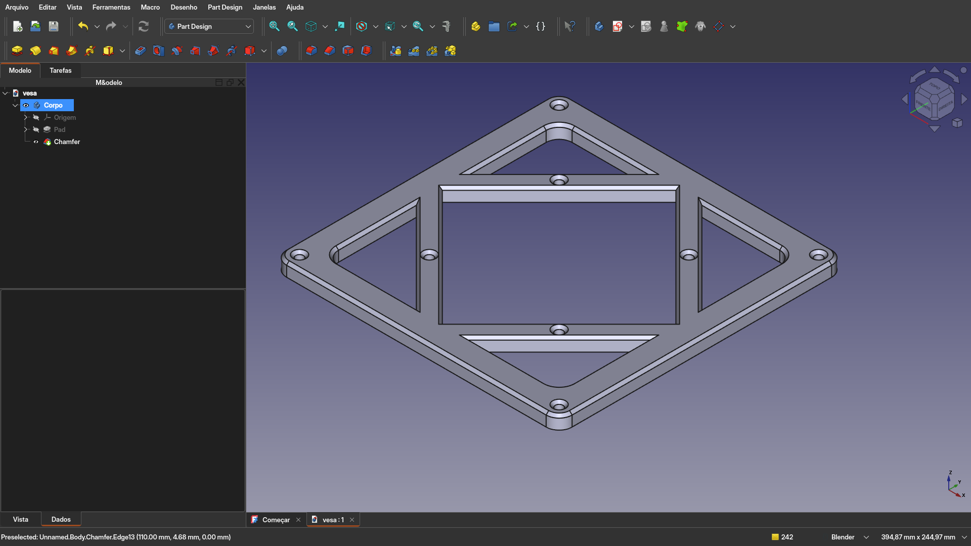
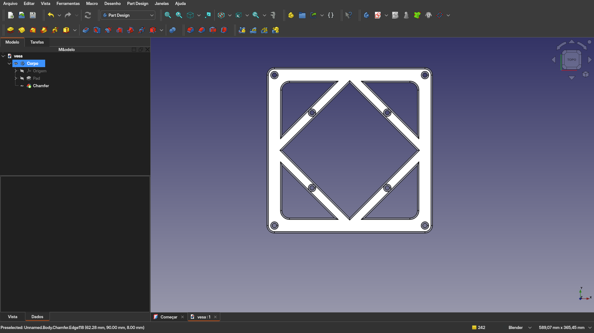
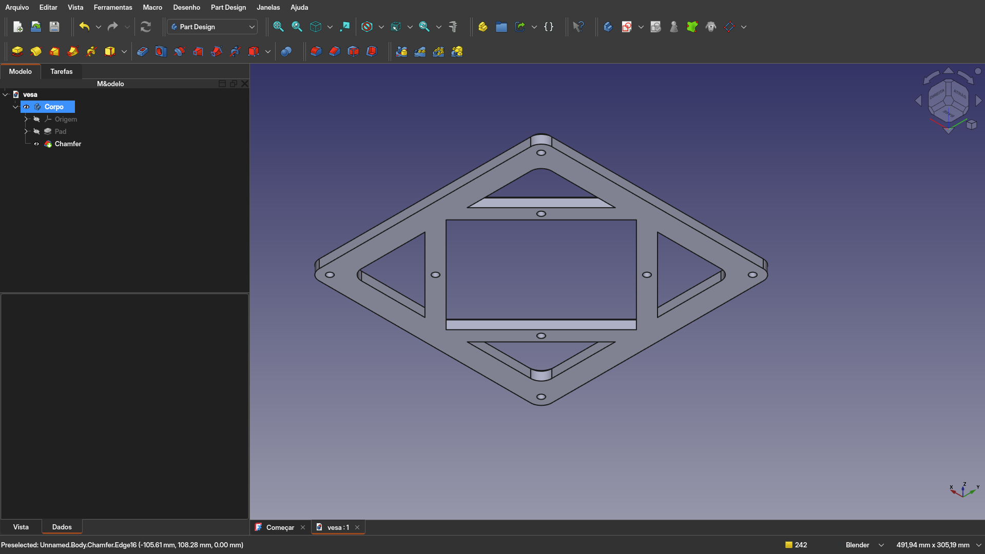
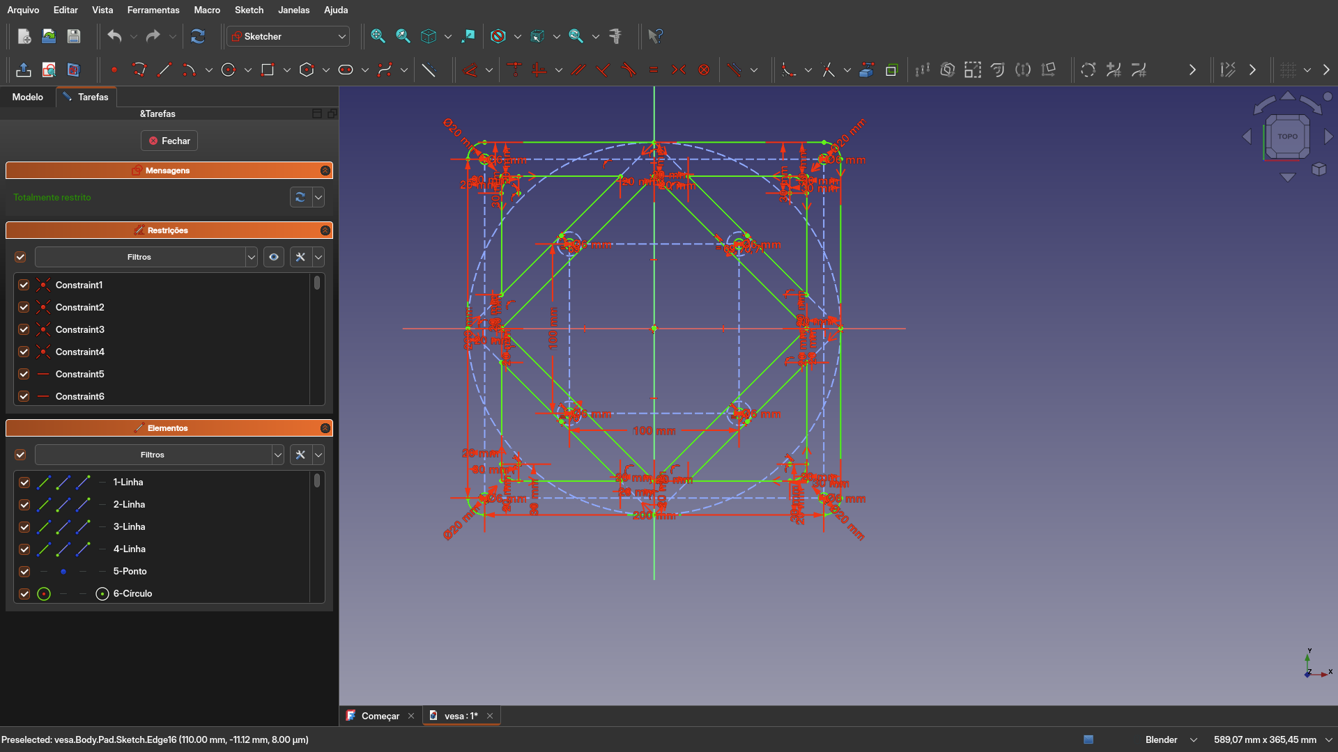
the sketch is quite a bit of a hellscape... i will see if i can figure out symmetry on the next iteration. Do you have any advice on how i can use better this program? it's been quite a bit since i haven't seen such a steep learning curve on a piece of software
9
10
11
12
13
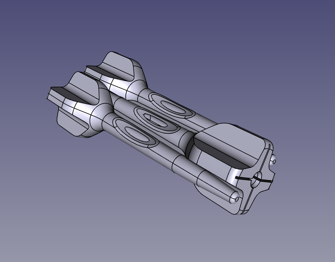
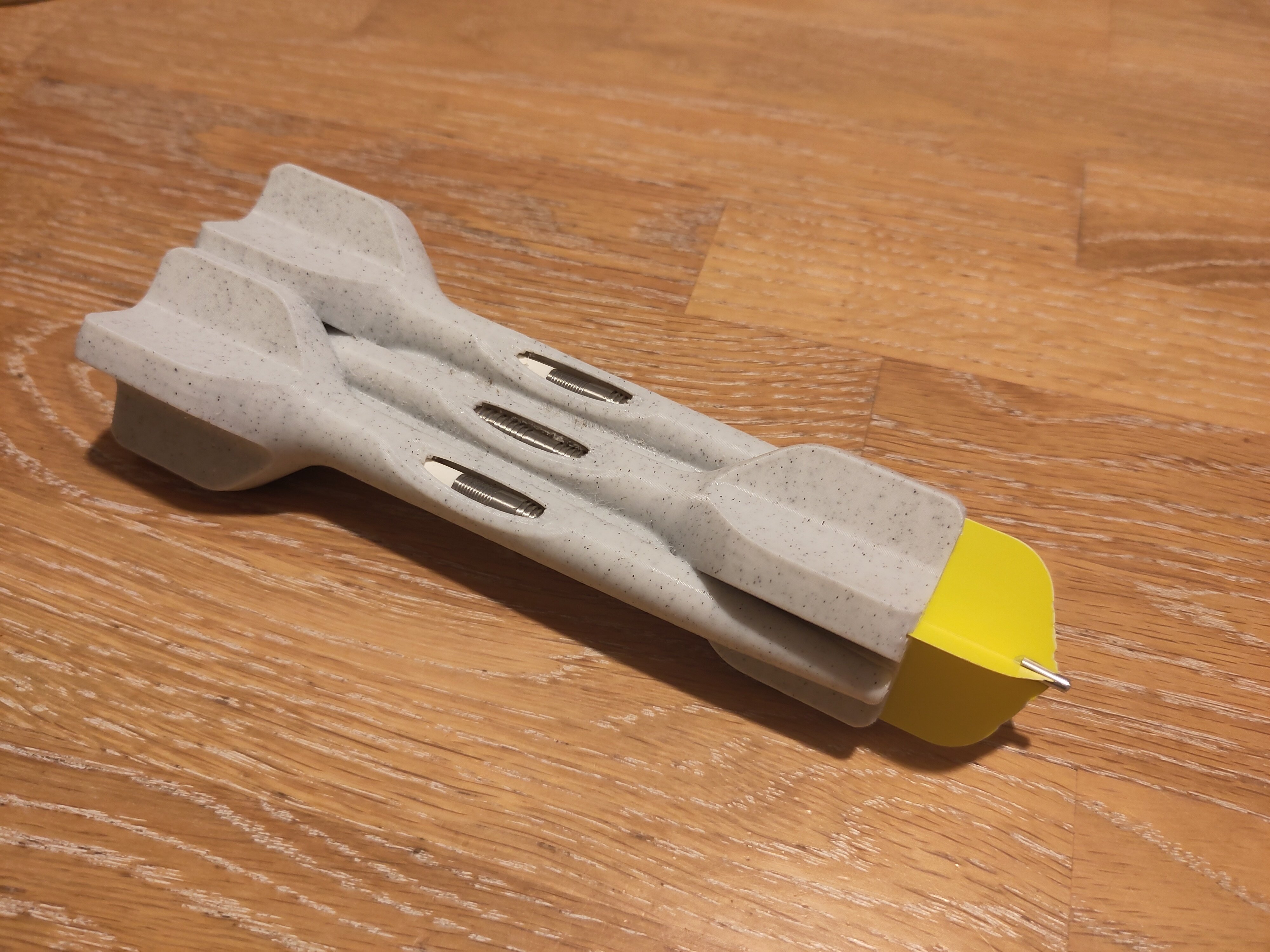
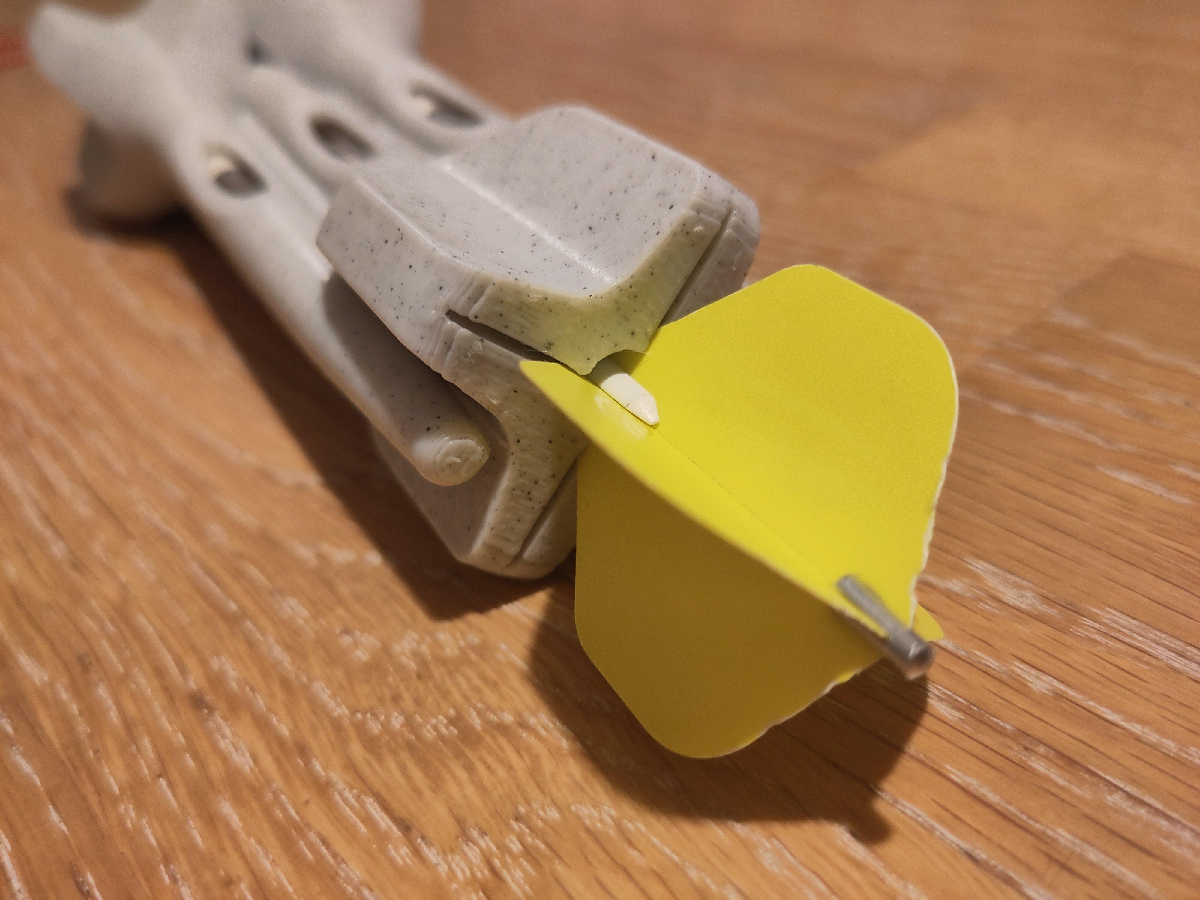
I'm designing a case for a dew-point ventilator controller to be 3d printed. The controller is implemented using arduino on an esp32. The project is based off of the code and HW implementation by Make Magazine Germany: https://github.com/MakeMagazinDE/Taupunktluefter. When starting out I was thinking this would be an easy project but it turned out that especially the lid with its lip and groove design and the parts fixations were not that easy. I'm excited to finally print it.
The file is parametric to some extent and the main footprint is based off of a master sketch. Many parts were imported as step files from grabcad. I used FreeCAD 1.0-rc1 which works like a charm for many things. Next thing I would like to do is to use the new assembly workbench. What do you think?
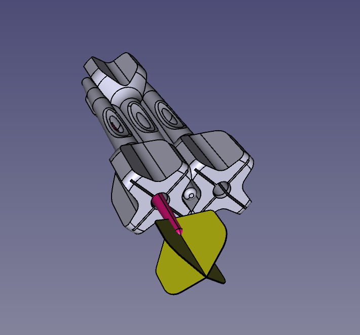
 Manual "Exploded view",
 Opaque view.

14
15
16
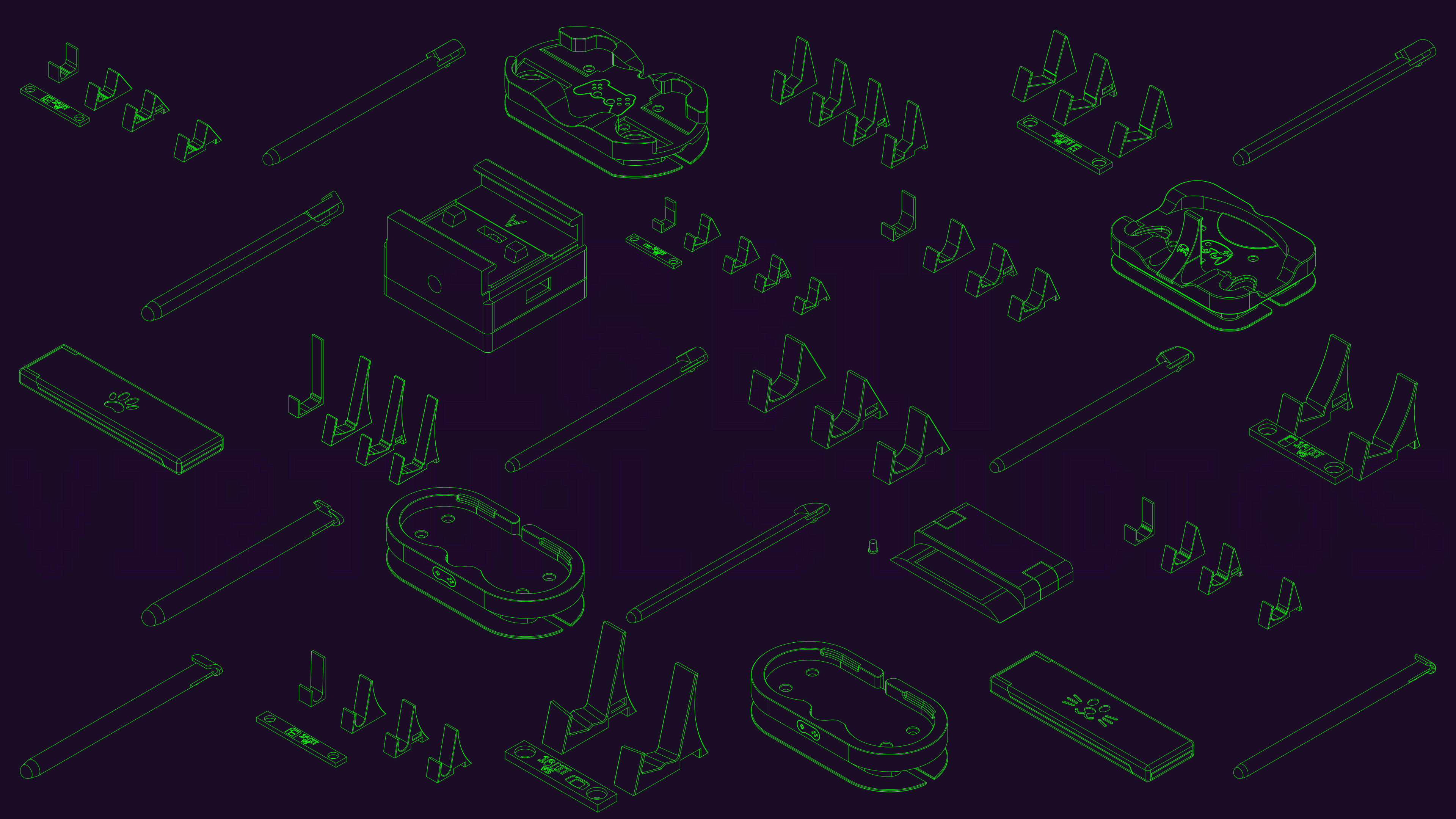
Thank you FreeCAD for not pay walling the ability to create technical drawings.
So what I did to make this was to create a technical drawing of all the designs I wanted and I made this photo in Inkscape.
Was designed to be a banner for my social media, but loved it so much that I'm just using it as my desktop wallpaper.
17
18
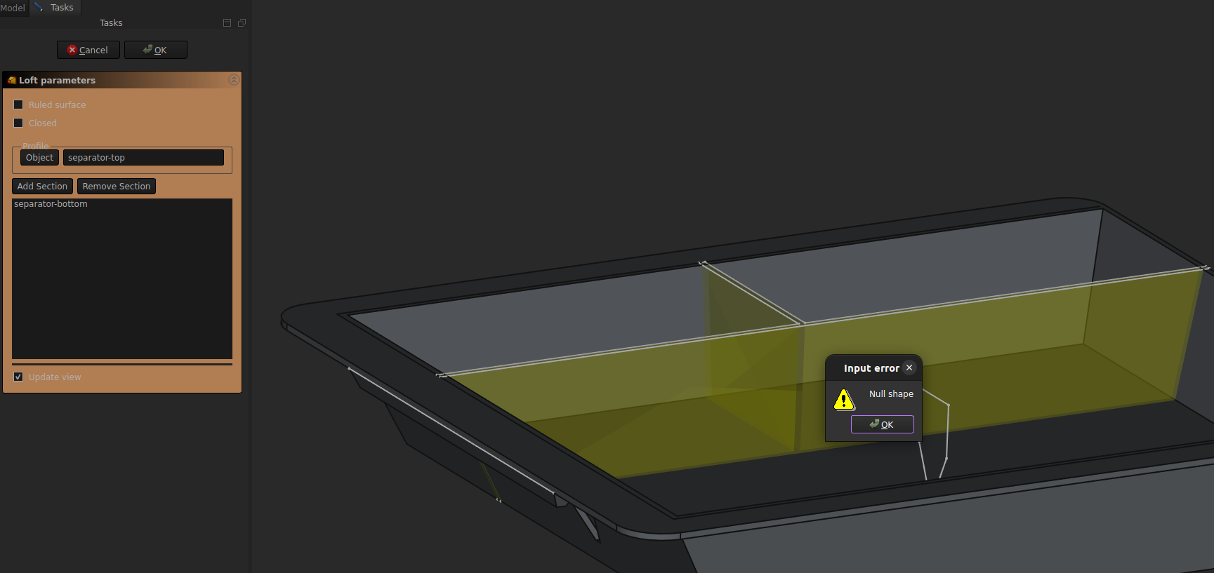
I'm working on a tray drawer (for the curious, it's for the Tesla Model Y front center box). Using FreeCad 0.22 dev, the model will be 3D printed.
With your help I could made it how I wanted. However as I'm a beginner with FreeCad, there's a lot of ugly things. So I wanted to work on this new iteration and clean it up as much as possible, mainly to learn the software.
I have 1 major problem: I can't make a loft between my to sketches to create the separators. And I don't understand why.
Another point I do not fully understand is the construction lines. Should I use the External Reference or a Carbon Copy ? I don't really like the carbon copy as there's to much things displayed and sometimes I'm lost and don't see my original sketch anymore. For example, my bottom separator sketch must be linked somehow to my bottom box sketch, so if I change the position of the bottom of the box, the separator will adjust automatically.
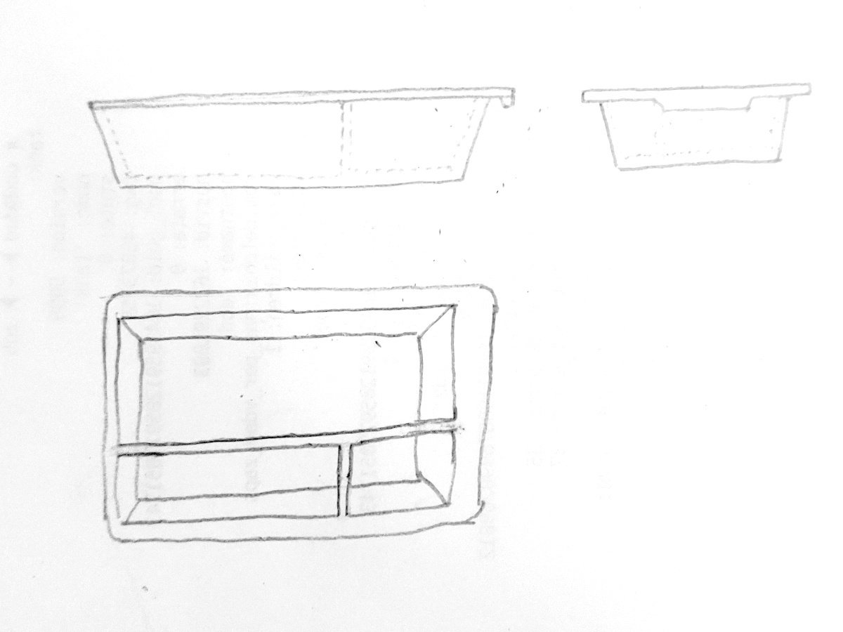
Here's an image of how the model should look (my previous iteration) https://imgur.com/a/H8on1MZ
and here's he file I'm currently working on. license CC0 1.0 (you can do whatever you want with it) https://drive.google.com/file/d/1WSgCSVhF1Io7ynhOXDkcO1hc8piln_mg/view?usp=sharing
19
I'm new to freecad, so far I made it this way :
Sketch a rectangle for the top surface, pad it, add filets for the corners. Then select to bottom face, make a new sketch, another rectangle, then a datum plane 40mm below, sketch another smaller rectangle, and make a loft between the two to create the bottom of the tray.
Now for the hole I made a rectangle on the top face and made a pocket with an angle.
Downside of this, the thickness of the walls is not equal. Ideally I'd like a 1.5mm thickness everywhere. And I'm not really sure how to proceed to make the separators inside the tray.
What is the most efficient way to do it? thanks
20
21
22
23
24
I got sent a bunch of lenses that are too small for the old frames I have. I thought it might be fun to try 3d printing my own frame arms out of ABS.
Modeling a lens is a bit challenging, or I'm just a bit rusty with freecad. I need a way to wrap/unwrap/flatten the curve to create the contours. For my purpose here I can get away with a rough lens shape that is simply mirrored and lacks some of the complex curves. It just bugs me when I can't model it properly...
The lens is not uniform thickness. The center is 1.8mm thick while the edges where the arms mount are 1.4mm. I want to try and make a nose piece because this is the one part that fails on these cheap glasses.
Anyways, sharing just because I can.

view more: next ›