3DPrinting

18874 readers
31 users here now

3DPrinting is a place where makers of all skill levels and walks of life can learn about and discuss 3D printing and development of 3D printed parts and devices.

The r/functionalprint community is now located at: or [email protected]

There are CAD communities available at: [email protected] or [email protected]

Rules

If you need an easy way to host pictures, https://catbox.moe/ may be an option. Be ethical about what you post and donate if you are able or use this a lot. It is just an individual hosting content, not a company. The image embedding syntax for Lemmy is ![](URL)

Moderation policy: Light, mostly invisible

founded 2 years ago
MODERATORS
1


First PETG 3d print in a while. Main body seems fine but overhangs are not. Unsure why. Need to investigate. (it's a phone stand, the central portion swings out and makes a triangle, holding phone in that curve.)

Stl https://www.printables.com/model/979455-collapsible-stand-for-phone-or-tablet

2
3


If you wanna print it yourself, the model is here: https://www.printables.com/model/1348194-4n-threaded-flat-head-screws-and-nuts-10-32-equiva

Design to be a drop in replacement for 10-32 screws with a much, much higher pitch. These screws are extremely easy to print, is reliable enough that it can hold some weight.

If you wanna print this yourself, you need to make sure that the screw is sideways, so if it breaks it's no on the layer lines.

Using them in my own prints which had metal screws and they are holding quiet well.

4


Had a weird black stain on a PETG print. Maybe it was mold? It seemed pretty penetrated into material. Tried windex, all purpose cleaning spray, dawn soap and couldn't get it out. Gave a tide pen a try and it scrubbed right out easily with that!

5


My favorite 3D printer just released a new puzzle box. Take a look and check our his designs. Would love to see what people think?

6


I have been using my Bambu A1 mini for the last several months without major issue, but suddenly I can't get anything to print. Even a benchy detaches before finishing.

I have scrubbed the plate with a fresh sponge, soap and water. I kept my filament in a dehydrator for a couple of days, then immediately tried to print.

There is a local problem, where an illegal landfill caught fire, and it can't be put out. I smell burning rubber all the time. Could that be the cause of the print failure? What else can I do?

7
63
submitted 6 days ago* (last edited 5 days ago) by [email protected] to c/[email protected]


Right now all it has is a plotter adding but I'm also making a mount for a mill and lasercutter. It's meant mostly for making circuit boards but should be able to handle other projects as well.

It's designed in FreeCAD and some parts were sourced from discarded laboratory devices from my job as well as a broken 3D printer.

Here's a link to the FreeCAD in its current form. I'm not happy about Google but this is to be shared for free so it's okay.

https://drive.google.com/file/d/1TaGmB2l-2IpyjhtpyuxbR6gJtIwyiHvx/view?usp=drivesdk

Right now it's a bit messy but I intend to post it to printables.com later when it's fully done.

The video is sped up 8x. I think it can handle this speed realtime as well.

8


Tldr: Did Bambu address the issue, and should I look into updating firmware now.

For context, I got a Bambu Printer just before they released the changes to improve "security" and have been on old firmware since. I was looking at the Bambu Wiki and saw this page that indicated that all of the important LAN functions would be opened up. Unfortunately it requires being on LAN only mode, but I've been on LAN only since January because of their changes so it doesn't effect me much.

I'm not dependent on their cloud features as I am home a substantial amount of the time and I have a server for when I'm not (to use home assistant or wtv). From my point of view the developer mode seems to address my issues, but I wanted to know some other people's thoughts on the whole controversy and how it was addressed by Bambu.

9


Designed in FreeCAD. I wanted to make a customizable screw and nut for my designs. Took me (on and off) weeks to get this working. But now that it does, I kind of want to test it to see how strong it is.

10


I just did my very first TPU print after years of printing PLA and PETG, and I've gotta say: That stuff sticks like a mofo on the textured PEI plate..!!
The print turned out great and the default profile in BS needed very little tweaking.
I'm currently using Fiberology MattFlex 40D.

What do you guys use to ease the removal?
I've seen normal glue sticks, IPA and liquid glue made for 3D printing, but I figured it would be cool to ask the fine people here.

If you do use glue: Do you stick with a smooth PEI or maybe something else?

All feedback is appreciated!

Thanks in advance!

11


Looking to get another printer that shall be printfarm compatible. What do I mean?

  • reliable
  • easy to service
  • excellent replacement part availability
  • affordable
  • affordable replacement parts
  • AMS (switching spools once it runs out & multi-color within a flat layer [not vertical/between layers])

Normally I would just buy another A1 mini (180€ without AMS) or P1S (650€ with AMS) but with recent issues with the printer & support quality & them banking hard on proprietary with Support staff who don't know what their error messages mean make me question if those are still the best option or if some other company meanwhile took the crown.

other spec:

  • approx. 256x256mm
  • exclusively used with PETG-filament
  • enclosed (keeping dust out)
  • network connected. ideally with a web service to use it remotely
  • in stock (this sadly disqualifies the Elegoo Centauri Carbon which seems to be the goto at the moment).
12
48
submitted 1 week ago* (last edited 1 week ago) by [email protected] to c/[email protected]


I gotta make these. They seem like they'd make good gifts.

https://www.instagram.com/reel/DLh1FwygMzv/

Edit Here's their link tree https://linktr.ee/TheKitKiln

Which leads to thangs https://thangs.com/designer/The%20Kit%20Kiln

13
14


I have a questions I haven't found answered anywhere, but maybe someone here can help out.

First, some background:

I have bought this silica gel with indicator a while ago and have used it in my AMS and also for storing my filament in ziplock bags.

I now want to dry some of the silica gel, and have looked at the various options there are. I want to rule out the use of my kitchen appliances, as I am not fully convinced of the silica with indicator being really fully non-hazardous. I also recently bought a Creality Space Pi dryer, which I would like to use for drying my silica as well. Of course I would need to print a container for that, and since I only have PLA and PETG available at the moment, I wouldn't be able to drive the dryer too hot.

Online you can find many different opinions about the ideal drying temperature for silica gel, ranging from 60°C to 145°C.

Efficient energy usage is no big concern for me with this, as my PV modules produce a lot of excess power during the current season.

Question:

What temperature should I dry the silica gel at, and does a longer drying time at lower temperature equal the same results as a quicker drying at higher temperature?

Or does higher temperature actually remove more humidity overall, which a lower temperature can maybe not achieve regardless of time?

15
16
73
Moire/Vernier Radius Gauge (www.printables.com)
submitted 1 week ago* (last edited 1 week ago) by [email protected] to c/[email protected]


I previously posted this on Reddit, since it reaches more people there (and I didn't want to post everywhere at once, as it makes it harder to keep up with the comments). Sorry about that.

This is a tool for measuring the radius of a circle or fillet from the outside; it uses a moire pattern of slots and lines to enable a direct reading of the values from a vernier scale.

A video of a broken-open version makes it a little easier to see how the moire and vernier features operate: https://i.imgur.com/Ku2nBkq.mp4

More photos of a slightly earlier version are here, including the tool being used for actual readings: https://imgur.com/gallery/moire-vernier-radius-gauge-design-3d-printing-ajy0GBg

I was inspired by this post: https://makerworld.com/en/models/1505553-adjustable-chamfer-gauge#profileId-1575605

which is a gauge which measures chamfers using a sliding probe. The same user had also posted a radius gauge, which worked similarly, but it was much larger, using gears and two racks in it to amplify the motion, which I didn't initially understand. I asked about it, and he pointed out that, because of the geometry of the probing, the slider only moves a small proportion of the length of the actual radius being measured--about (sqrt(2)-1), or 0.414mm per mm of radius. Since we're drawing the marks with a 0.4mm nozzle, it's not really possible to make marks that close together and still have them readable.

So I thought, I bet you could fix that with a vernier scale. And then I had several thoughts all at once--that a lot of people are kind of scared off by vernier scales, and also that I bet you could fix that with 3d printing using the relationship between moire patterns and vernier scales. I don't think I've seen this done before, but it probably wasn't really practical before 3d printing. Arguably it's not entirely practical now, as the deep slots and parallax effects can make it a little hard to actually see the markings. But it was a fun experiment, and I think the result is eye-catching enough that it's probably got some educational value in getting people to actually think about how it is that vernier scales work. (It might even have educational value for things like number theory...e.g., it's important that the vernier factor involve relatively prime numbers, in this case 9 and 10. Can you see why?)

Anyway, hope folks here find it interesting too.

17


Bed levelling or in true terms bed traming is adjustment to how parallel the hot end nozzle travels across the surface of the print bed.

With frustration and perceverence, I was able to achieve perfect first layer adhesion, reduced z-wobble and good prints.

I would like to share a simple concept and process on how I achieved true traming without continuous adjustments and I only redo this process only if something major disturbs the printer and bed. This is the manual process which I use to tram both my Ender 3 V2 Neo and Neptune 4 Plus. Refinement and fine tuning can be achieved via software and manual spacing.

I am not an expert, but only sharing my observation and results from learning from my mistakes.

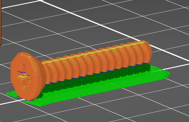
The picture above represents a cross-section of the nozzle and print bed assembly with a blue line representing true levelling (traming).

The print bed is made of an alluminum plate. Due to thermal expansion and contraction, metal will become distorted in it's natural state if without reinforcement. When heated, metal expands and when cooled metal contracts.

Before attempting this process, print and install appropriate adjustment screw locks for your specific printer and that you have calibrated E-Step of the extruder and Temperature. This is the minimum to satisfy your level but not the complete calibration process of your printer.

Levelling process and concept

The first picture shows, the bed is bowed downwards, and all the adjustment screws is all the way down.

All of my 3D printers as they come out of the box, the bed has a downward bow. You can measure this from the middle of your X-axis gangtree if its square down to the bed and repeat from the X-axis gangree to the edge of the bed.

The second picture show, as you wind all the adjustment screws all the way up, force is applied to the edges of the print bed making the bed bow upwards. You can verify this by measuring from the X-axis gangtree as described previously.

*** Take note, the first two pictures is the bed 'Unheated'.

When I'm traming, I do the usual paper (feeler gauge 0.05mm) technique to get my Z-offset and evenly adjusting the screws between the nozzle (unheated) to tram the print bed before auto-levelling.

From the third picture, the yellow line represents my perceived traming - traming the print bed in relation to true level.

Once I auto-level and the bed heats up, due to thermal expansion, the bed bows upwards. The problem here, is that the Z-offset will compensate for any distortion of the bed, but when the nozzle prints either side of the bow, you may think your layer is level, in fact the first layer is barely adhering, due to the Z-offet has it's level computed from the bow when auto-leveling.

*** From my experience, this is why I get problems with layer adhesion.

The fourth picture, I adjust my adjustment screws, so my print bed is just a tad below actual level. As you can see the yellow line has a downwards bow. The reason for this, is to compensate for the bed bowing up to achieve true level when the bed becomes 'heated' during auto-level.

*** I have reduced Z-wobble because how this process helped to damped or reduced the Z-axis movement and have better first layer adhesion.

Check for level and first layer quality

  • Dowload first layer (100 x 100) 3d file and slice.

  • Print the first layer and adjusting the Z-offset at the same time.

*** What you are doing is setting the correct filament extrusion for the first layer. What you want to achieve is consistent layer that has no over or under extrusion.

*** For under extrusion, the filament layer is apart from each other and eventually, the further you adjust the Z-offset away from the bed, the filament will not adhere and detatch itself from the bed.

*** For over extrusion, the filament will bulge around the nozzle, causing raises of streaks above the surface of the first layer. The closer you adjust the Z-offset towards the bed, more filament will streak and eventually no filament will be extruded.

  • Once you have justified the correct Z-offset, let it finish the print.

  • Print another layer without adjusting the Z-offset.

*** If the result of your first layer test is consistent in the layer without under or overextrusion symtoms, your print bed is level.

*** If you find raise streaks on areas of the print, that part of the print bed is high. If you find blistering raises, that part of the print bed is low.

  • Adjust as per levelling process above until you achieve a nice first layer.

You can make refinements to the actual bed before auto-leveling by adding alluminum tape or something thin enought to act as spacers if your bed is badly distorted. If you cannot achieve your desired first layer after many adjustments, then there is a probability that part of the bed is distorted enough you need spacers.

To fine tune after auto-leveling you can use bed meshing software like klipper if you have it on your printer or have modified it have these priviledges. I only use this method to really hone it to get a perfect print. But in general manual levelling will be suffice.

Please let me know if this has helped

18


This has been through many days of iterations and designs. Most involved over center mechanisms or wheel levers before this design dawned on me. The bottom right is how it prints. The "spring" is a double forked 10mm bridge in the last few millimeters inside the enclosed print. The visible "clamp" is connected to the spring by forking into two paths that branch beside the tube that the spade terminal is inserted through. The clamping force is not great but it is sufficient for a reliable basic electrical connection for bench testing. The pictured driver is a very small tweeter and is barely held in place with both wires inserted between the print and spade terminal.

I wanted something that would fit on the faceplate of the little hacked audio amp enclosure I have been designing. I think 6 of these will barely fit across the front and under the actual circuit board assembly.

This one might be worth the hassle of setting up an account and sharing on printables if it does not require the goggle server connection like it did in the past when I tried.

The thing is, I dial in my prints to 0.3mm clearances and this absolutely requires that clearance. I do not care to print other people's designs because most are really terrible for things like supports, designing for 3d printing, clearances, and general slop. I'll occasionally toss someone else's STEP or STL in FreeCAD and rebuild the thing but I usually just use some conceptual idea of anything I see elsewhere. I think with this one, I could share it as a negative Boolean STEP file to be most useful. Then it would only require others to import and do a boolean cut operation to use the design. Maybe I will do so if it works out well in my enclosure with 6 of these all resolving well and functional. What do you think, would you ever care to find and print something like this in one of your designs? Do you think anyone would even understand the value of printing such fundamental componentry instead of buying hardware and gluing it together with a 3d printed design? Like, this could easily be configured to use a loop of solid core copper wire as the connector terminal for a low voltage bench power supply that requires no other hardware.

Also, I had a rather irritating encounter with Dessalines (the Lemmy Dev) on ML a few days ago. I want to move off of Lemmy but I kinda like the rest of you, so maybe piefed is an option. I haven't looked into it deeply as I thought rust was worth supporting more, however empowering these guys as authoritarians is not on my list. I'm in a position to move this community if people want but like I always say, I'm just the janitor here. I do not matter. I would just as soon give this place to someone else if that is best for the community. I only want what is best for all, which is probably stability first and foremost, but if you feel otherwise, maybe mention it, maybe we'll make it happen.

19
20


I have recently replaced the motherboard of my Ender 3 V2 Neo from a Creality 4.2.2 to 4.2.7 motherboard.

With all the frustration, I was left with the Creality splash screen with numbers in the bottom of the screen following contents which got me nowhere.

There's no streamline instructions showing how to install this firmware onto a clean motherboard so I decided to make this thread and explain the process on how I successfully made the installation.

I am by no means an expert or advicing on programming or 3D printing, so please don't criticize this process.

I hope below can be of help to those with the same printer and similar issues.

  • Format micro SD Card

Note: The motherboard is very picky with micro SD cards. For the installation I used: 2GB Sandisk micrSD. Click on this link for how to choose the correct micro SD card: https://www.youtube.com/watch?v=B_-wZxqGprE

  • Format micro SD to FAT32 with 4096 bytes (Do a full format not a quick format)
  • Download 4.2.7 Creality Firmware

-- Ender-3 V2 Neo-Marlin2.0.8.3-HW-V4.2.7-SW-V1.1.5-CR-Touch-Filament (260 ℃)

-- Ender-3 V2 Neo-Marlin2.0.8.3-HW-V4.2.7-SW-V1.1.8-CR-Touch (260 ℃)

-- Ender-3 V2 Neo-Marlin2.0.8.3-HW-V4.2.7-SW-V1.1.8-CR-Touch-SpiritExtruder (300 ℃)

Note: I chose the V1.1.5 from the list for simple installation (The installation for the other versions I believe is similar)

  • Screen Firmware Installation
  • Open the version file and open the 'Screen' folder.

  • Copy the 'private and TJC_SET' folders and the firmware.zlib file to your formatted micro SD Card. (This are your screens firmware)

  • With the printer off, unscrew the four screws in the back of the screen.

  • You will find a micro SD slot when you open the back. Insert the micro SD into the slot. Make sure the screen cable is still connected to the screens mother board.

  • Turn on your printer. The screen will have a white background and the process of installing the firmware. 'Successful 100%' will indicate on the screen once finished.

  • Turn off the printer and remove the micro SD from the card slot on the screen.

  • Screw the back with the four screws removed earlier.

  • Motherboard Firmware Installation:
  • Delete all the screen firmware from the micro SD card.

  • Copy the: Ender-3 V2 Neo-Marlin2.0.8.3-HW-V4.2.7-SW-V1.1.8-CR-Touch-SpiritExtruder (300).bin

  • This is your motherboards firmware.

  • With the printer off, insert the micro SD card in the front slot of your printer.

  • Turn the printer on

  • You will see the Creality splash screen and a loading bar as the firmware loads. This will take a couple of minutes.

  • A successful installation will take you to your printers settings menu.

  • Check the firmware in the info section of your printer settings.

  • Turn off the printer and remove the micro SD card.

  • Proceed with how you would normally print.

Please let me know how this helped.

21
22
23
24
29
submitted 2 weeks ago* (last edited 1 week ago) by [email protected] to c/[email protected]


TLDR: thinking about getting a new printer with a budget of maybe €1200, mostly for toys and hueforge. Preferably FOSS

I got an Ender 3 Pro three years ago as my first printer. Over the years I've printed plenty toys and some occasional functional parts, and it's been mostly pretty good. It's developed problems now and then, but I've been able to fix them.

I've recently played a bit with HueForge, it's this software that allows you to print really nice multicolour images by blending filament colours. This is doable by printing in super thin layers. It worked really well on the prusa mk4s at work, but not so much on my printer. Extrusion is just not consistent enough after swapping colours, or when there's a lot of retractions/deretractions.

I've gotten a bit tired of all the limitations the Ender 3 Pro has. I was looking at a Prusa mk4s with mmu3, since I enjoyed assembling the mk4 at work, and it's been working so well, even for the colleagues who don't know much about 3d printing. Although, for personal use, do I really want to pay the premium price for that level of reliability and longevity? A lot of budget brands do offer multi colour capable printers these days.

But I also feel pretty tempted to try building a Voron, and while I was looking at those I saw some IDEX printer that look so cool lol. And there's also the Enderwire that can make use of my old Ender 3 Pro...

Please help.

Update: I went and ordered a QIDI Q1Pro. My partner and I agreed to get a Voron kit and build it together for Christmas, I'll figure out what multi-mterial system to go for after that. Hopefully the Bondtech INDX

25
28
submitted 2 weeks ago* (last edited 2 weeks ago) by [email protected] to c/[email protected]


I've begun printing more minis for TTRPG, and since i only have a cheap bedslinger that's what I'm using.

Normally I've just stuck with minis designed specifically for supportless FDM printing, but I wanted to try my hand at something else and went with this Minotaur

fresh from the printer, supports all over

supports removed front

supports removed back

There's still a bit of post-processing before priming and painting, but I'm actually pretty happy with the quality, considering it was done on a $200 entry-level printer.

Printed in eSun PLA+ with a 0.2mm nozzle and 0.08mm layer height, it took just short of 9h to print it.

view more: next ›