cross-posted from: https://lemmy.dbzer0.com/post/26703241
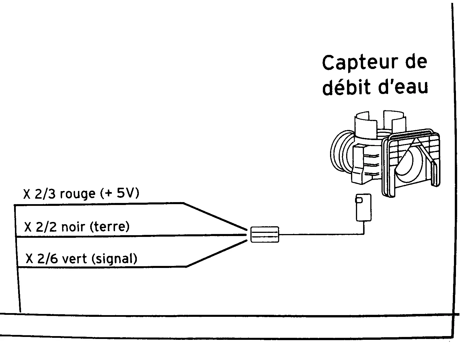
This diagram is from the service manual of a combi boiler. It’s a flow sensor which detects whether hot water is running, which is then used to trigger on-demand heat and switch a diverter to take radiators out of the loop.
In English, the diagram shows:
- X ⅔ red wire (+5V)
- X 2/2 black wire (ground)
- X 2/6 green wire (signal)
I need to know what those fractions mean. I took the voltage measurements in this video:
I cannot necessarily trust the model in that video to have the same specs as mine. My voltmeter detected 4.68 V on the red input wire showing that the sensor is well fed. The green “signal” wire is supposed to be 0 V at rest and 2 V with water running (or I think the reverse of that is used in some models). In my case the green wire is ~1.33 V at rest and ~0.66 V when water is running. I need to know if these readings are normal as I troubleshoot this problem.
update
@[email protected] and a couple others gave the answer I was after. Then @[email protected] helped solve the underlying problem. The theory that the sensor was fine but the board was not drove me to test the sensor in isolation. The sensor gave correct output in isolation. Then I connected it back to the motherboard to retest and reconfirm that it’s still broken. But it actually worked. The hot water suddenly and mysteriously works now. I guess the act of draining the water and unplugging the connector then reconnecting and repressurizing caused it to work. It may be temporary, since in the past it was hit or miss whether it would work.
Read your post again, and your readings are of course not in line with what I laid out. Are you measuring the sensor in-system?
If you are, the sensor might indeed be faulty. If you aren't, you probably need a pullup resistor on the output pin.
Yeah, if by /in system/ you mean connected to the board. I didn’t mess with anything other than to stick my probes onto the wires. The boiler is not switching on to heat water and it acts just as if it is not detecting that water is running. So a broken flow sensor was one of the theories. And since the readings seem quite off from what’s expected I guess buying a new sensor is the right move.
Once I get it removed I’ll see if it looks like I can rebuild it but I don’t expect that to go well. I may not have to waste it though. Considering the at rest voltage is double the running water voltage, it’s still detecting water running. It’s just not giving the voltage the board expects. So one idea is maybe I can repurpose this to turn on a shower light when the shower water is running.
If I had an electronics background I would probably try to do a makeshift gadget that converts 0.66 V to 2V and 1.33 V to 0 V. Then I wouldn’t need a new sensor (which could cost €100.. i’ve not checked locally yet but online prices are looking terrible).
With better tools, it would be easier to troubleshoot more precisely. An oscilloscope would help you understand what's going on, for example.
From what you describe, I'm actually starting to suspect the other end (the controller?) to be the problem.
One idea you could try before buying anything is to disconnect the sensor, supply it with 5V and ground (double check with data sheet!) and see what's happening on the output when there is flow. If you don't measure anything, as I would expect since the pin alternates between a floating state and ground, you then add a 10k or 50k ohms pullup resistor between 5v and output and measure again, and should get the levels you expected to see in the first place.
Don't know if you're comfortable doing this, but maybe you can find somebody to help you out?
It shows 5V on the diagram but I don’t think that’s precise. I measured the red wire at 4.68v which is around what the guy in the video got in his test. Since the board is part of the circuit I suppose I cannot rule out the board as a problem. Testing the sensor in isolation will be rough going because it’s a proprietary joint. So I would have to get a tight rubber hose and fit that onto a garden hose. For powering it I have a switchable ac adapter with a 4.5 V setting. Or I can maybe get 5V off a USB charger or ATX PSU from a PC. My multimeter does not have a frequency function but I can see from the video that it would be useful for this so I might look for 2nd hand multimeter at the next street market, though that will set me back a week (OTOH might be worth it if it helps diagnose this in a way that helps avoid buying the wrong part).